Stuart Turner 6A - Crankshaft Casting
-
RMB5241
- Just Starting Out

- Posts: 7
- Joined: Wed Jun 08, 2011 2:44 pm
- Boat Name: No Boat Yet
- Location: West Midlands UK
 Stuart Turner 6A - Crankshaft Casting
I have heard mention of a one piece crankshaft casting available for the Stuart turner 6A engine .......... any leads on where I might get my hands on one?
Robin
Steam - Water vapour as usually seen rising from the front of my Land Rover!
Steam - Water vapour as usually seen rising from the front of my Land Rover!
-
Lopez Mike

- Full Steam Ahead

- Posts: 1928
- Joined: Wed Dec 07, 2011 6:41 am
- Boat Name: S.L. Spiffy
- Location: Lopez Island, Washington State, USA
Re: Stuart Turner 6A - Crankshaft Casting
In an engine this size, I have found it to be far less work to build a crankshaft from individual parts and then press it together. The original crankshaft castings/forgings supplied with the rest of the Stuart engine kits are just too much trouble to use. I have a box of them. At least I would consider machining my own from a large section of bar stock with three centers on the ends.
I would not be at all frightened of assembling it with Locktite either. I have built several Stuart engines up to and including a #1 this way.
I did try a motorcycle racing engine this way but the temperatures were too high and the Locktite failed. Not immediately but eventually. This was a three cylinder 750cc two stroke 9000 rpm engine though. A #6 runs in a rather different regime!
Mike
-
Mike Rometer
- Full Steam Ahead
- Posts: 936
- Joined: Sat Aug 13, 2011 6:41 pm
- Boat Name: B.N.Y.S.
- Location: Middle Earth
Re: Stuart Turner 6A - Crankshaft Casting
I was taught that the best crankshafts were not cast, but forged.
Retirement is about doing what floats your boat!
A BODGE : - A Bit Of Damn Good Engineering.
A BODGE : - A Bit Of Damn Good Engineering.
-
Lopez Mike
- Full Steam Ahead
- Posts: 1928
- Joined: Wed Dec 07, 2011 6:41 am
- Boat Name: S.L. Spiffy
- Location: Lopez Island, Washington State, USA
Re: Stuart Turner 6A - Crankshaft Casting
In situations where the stresses are high (Internal combustion engines, for instance), forging is a useful solution. The lines of stress sort of follow the grain of the material which make less likely that there will be failure. However millions and millions of automobile cranks are cast with a failure rate approaching zero.
In our low speed engines which are operating at about the same loadings as a car jack, I would be startled to find a broken crankshaft. Running true is far more important and being able to machine the thing is very important! Machining those darned cranks that come with a Stuart engine is quick way to improve your specialized vocabulary. It's like trying to machine a noodle! There is a reason that automotive cranks are ground to dimension.
The beauty of making your own in bits and pieces is that you just buy common drill rod for the main shaft and crank pins and cut it to length. Then make the webs from larger bar stock. I drill the holes for the shafts first. Then mill away the stuff that doesn't look like a balanced crank and then part them off like cookies. I make a special collet to hold the crank webs while I face them off smoothly. The next trick is to bond the whole thing together using the crankcase as a jig. If you have done a decent job of getting the main bearings in line, this will insure a finished crank that runs dead true.
Locktite and its competitors need some clearance to work. Read up on it. Prepare the surfaces properly. Clean and Prime is Locktite's recommended stuff. Probably death to your liver or something. Smells horrible!
I have built #5 shafts this way with drilled oil passages from the main bearings to the rod bearings. One was for use with a slinger system a la Strath Steam and another to use a two stroke motorcycle oil injection pump for lubrication. Both engines were for generator duty.
I envy you owning a #6. I've always wanted one.
Mike
-
steamboatjack
- Full Steam Ahead
- Posts: 283
- Joined: Fri Nov 20, 2009 8:02 am
- Boat Name: grayling
- Location: Cumbria U.K.
Re: Stuart Turner 6A - Crankshaft Casting
Please don't make crankshafts like this! And don't use Loctite! The torque required of steam launch engine is very high and cannot be compared to model engines. This is a job requiring some design considerations, I did a small contribution to the funnel giving guidelines which I copied onto this forum but it may have been in the old section. At the risk of boring everyone I will repeat it.
Regards Jack
In the pages of funnel there has been numerous items concerning crankshafts and their construction for steamboat engines and probably more tears shed than in any other part of construction. My personal view, is that the methods discussed below are the most suitable and I would not consider any other method bearing in mind that steamboats often operate in conditions of a very high torque to power ratio what is known as a “torque rich” condition, this is often due to the idea that even small boat engines should run at 200 or 300 revs per minute turning a huge propeller, a view I do not necessarily share.
Solid construction, many crankshafts are machined from solid using stock material, If you have a Dean Smith & Grace or another fine large capacity lathe made in Yorkshire, or the midlands all well and good. Carbon steel should be selected of at least 600 N/mm2 tensile strength. I use EN8 generally for this type of work, its easy to machine and is of sufficient strength providing the dimensions are sufficient and (most important) the change in sections are provided with generous radii. The radius at the crankpin and main journals should be at least 0.125 of the journal diameter and the bearings should have a chamfer sufficient to clear this. Ideally the journals should be finished on a crankshaft-grinding machine, automotive repair engineers can usually do this, the grinding process will accommodate the radii and there is no need to leave the crankpin centre bosses on. Modern crankshaft grinders use a wheel head that reciprocates to suit the eccentricity of the crankpin in question.
Should you be a dab hand at pattern making, then S.G. iron could be used although bear in mind the strength of the material will be less than EN8 and the radius is even more important. Many years ago at marine engineering college I saw a film that showed the construction of a crankshaft for a Doxford oil engine (I don’t use the “D” word as the oil engine was invented by Herbert Ackroyd Stuart an Englishman). Anyway the chaps at Doxford & Sunderland had a large forging which was to be made into two crank throws with a main journal between (part of a crankshaft) this was a U shaped forging and one leg of the U was lowered into a pit and the centre part heated up to red heat, the other leg was then twisted though a large angle (forget what) to form a two throw piece. If this can be done with a forging weighting many tonnes I am sure it could be done with a profile cut slab of EN8 to form a two-throw crankshaft. Obviously stress relieving and a large machining allowance are essential, but it could save on material for anyone wishing to try (I have never done this myself).
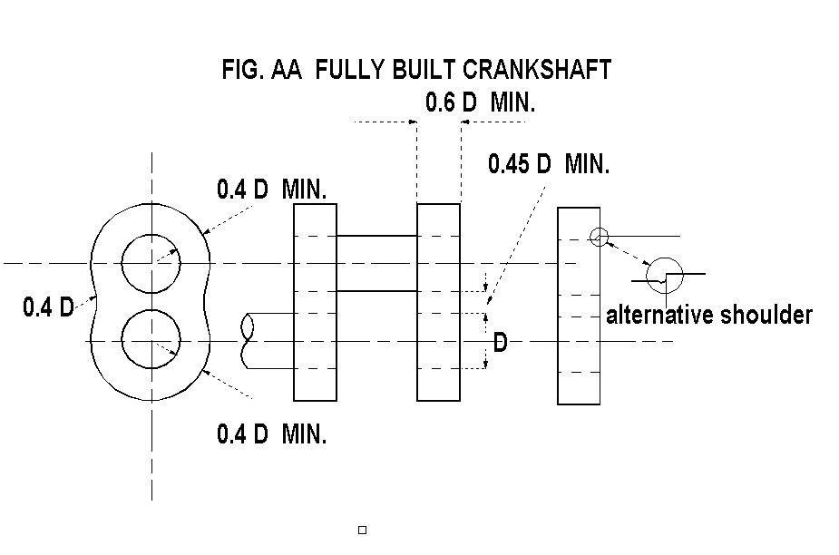
Fully built construction. A fully built crankshaft is one where the main journals and the crankpins are shrunk into holes in each web. The main shaft is kept as a single piece until the shrink process is complete and then cut out before final skimming of the web inner faces if required. This type of construction has the drawback that the fillet radii as mentioned above cannot be used. Many large marine steam engines were built by this method using a web profile similar to fig AA. These were often fitted with pins installed axially along the join between the main shaft and the web. The fitting of any kind of pin is NOT recommended. In the case above the pin could in fact compromise the integrity of the interference fit and pins fitted radially are of limited use as torque transmitters, any pin hole produces a stress point, don’t use them. The same could be said of oil holes, these should only be contemplated with solid crankshafts and if used all drilled ends should be carefully radiused. The surface finish of shrink fits should be as good as possible, grinding is best but careful turning and polishing will suffice, the idea that a “rough” surface will grip better is nonsense and purposely roughed surfaces should be avoided.
The correct interference fit is 1/600 of the diameter concerned.
i.e. 1.67 thou per inch of diameter, obviously a tolerance needs to be used but it should be a close to this as possible. The selection of material is very important and 600 N/mm2 tensile strength is again the minimum particularly for the webs. The minimum web thicknesses both axial and radial and the ligament width between pins shown on the drawings must be adhered too to avoid over stressing the webs, which would lead to failure of the shrink fit.
I personally would not use the fully built method unless I was constructing a very large shaft, as I believe the “semi built” method is superior,
Semi-built construction. This is the method used for large marine crankshafts weighing 300 tonne or more and transmitting over 100000 H.P. the main reason for this method is two fold.
A) A large radius can be accommodated on the crankpin/web corner. And B) The vertical distance between the diameter of the crankpin and the main journal can be made small (which is not possible with two adjacent shrink fits) and therefore the journal diameters can be made larger for a given stroke of engine.
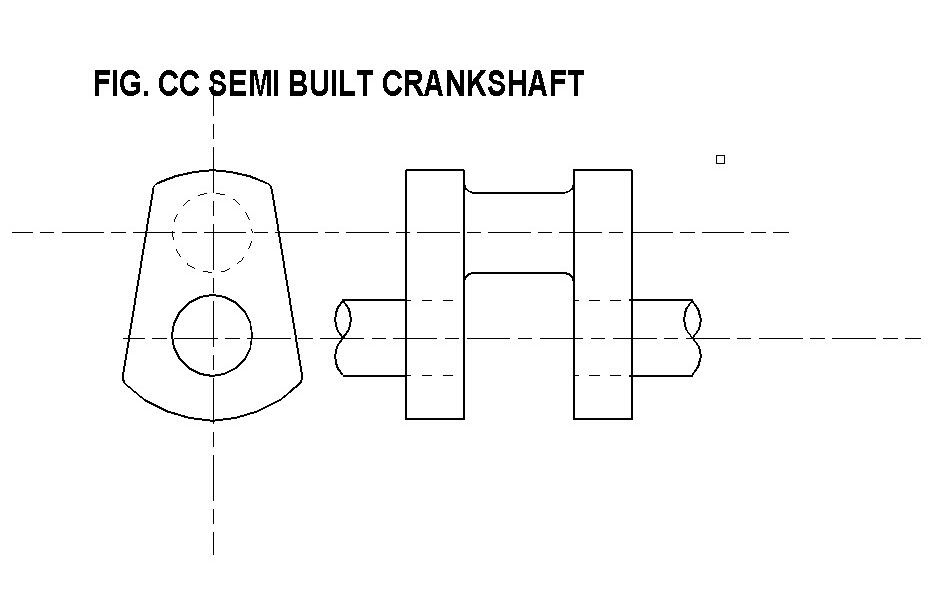
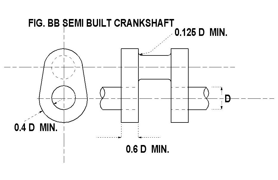
Each cylinder unit consists of a pair of crank webs and the crankpin machined from solid, these are then shrunk onto the main shaft as in fully built construction. If the profiles shown in fig BB or CC are used the web units can be machined from round stock with a minimum of waste and machining time. As with solid construction it’s often easiest to chop out the bulk of the crankpin area using a milling machine and dividing head rather than the lathe.
Fully built using vacuum brazing. I am building two engines currently which came with partly finished crankshafts, this has apparently been vacuum brazed, I am not familiar with this construction method but believe it is a “high tech” process used a lot in industry. The integrity of the brazed joints is probably good but the design problems of the lack of radii are still a concern especially as this is a three-throw crank running in six main bearings, the cranks are radially pinned but this is probably for assembly reasons. The photo shows the second crankshaft as received from the brazing process, I intend to reduce the size of the hideous balance weights and fillet out the right angle internal corner on the webs, a very poor idea both mechanically and aesthetically, had I built these myself I would not have fitted balance weights at all on a three throw crankshaft.
Should you consider the use of balance weights I would suggest the web construction as in fig DD this is a fairly traditional design for launch engines, additional weights can be attached on the insides provided the tapped holes are well away from the shrink fit or they can be part of the web if fully built, either way its obvious that the weights should clear the connecting rod. Personally I believe that weights even on a two crank ninety-degree shaft are rather a waste of effort as you can never fully balance such an engine without recourse too much complication, but that’s another subject.
Regards Jack
In the pages of funnel there has been numerous items concerning crankshafts and their construction for steamboat engines and probably more tears shed than in any other part of construction. My personal view, is that the methods discussed below are the most suitable and I would not consider any other method bearing in mind that steamboats often operate in conditions of a very high torque to power ratio what is known as a “torque rich” condition, this is often due to the idea that even small boat engines should run at 200 or 300 revs per minute turning a huge propeller, a view I do not necessarily share.
Solid construction, many crankshafts are machined from solid using stock material, If you have a Dean Smith & Grace or another fine large capacity lathe made in Yorkshire, or the midlands all well and good. Carbon steel should be selected of at least 600 N/mm2 tensile strength. I use EN8 generally for this type of work, its easy to machine and is of sufficient strength providing the dimensions are sufficient and (most important) the change in sections are provided with generous radii. The radius at the crankpin and main journals should be at least 0.125 of the journal diameter and the bearings should have a chamfer sufficient to clear this. Ideally the journals should be finished on a crankshaft-grinding machine, automotive repair engineers can usually do this, the grinding process will accommodate the radii and there is no need to leave the crankpin centre bosses on. Modern crankshaft grinders use a wheel head that reciprocates to suit the eccentricity of the crankpin in question.
Should you be a dab hand at pattern making, then S.G. iron could be used although bear in mind the strength of the material will be less than EN8 and the radius is even more important. Many years ago at marine engineering college I saw a film that showed the construction of a crankshaft for a Doxford oil engine (I don’t use the “D” word as the oil engine was invented by Herbert Ackroyd Stuart an Englishman). Anyway the chaps at Doxford & Sunderland had a large forging which was to be made into two crank throws with a main journal between (part of a crankshaft) this was a U shaped forging and one leg of the U was lowered into a pit and the centre part heated up to red heat, the other leg was then twisted though a large angle (forget what) to form a two throw piece. If this can be done with a forging weighting many tonnes I am sure it could be done with a profile cut slab of EN8 to form a two-throw crankshaft. Obviously stress relieving and a large machining allowance are essential, but it could save on material for anyone wishing to try (I have never done this myself).
Fully built construction. A fully built crankshaft is one where the main journals and the crankpins are shrunk into holes in each web. The main shaft is kept as a single piece until the shrink process is complete and then cut out before final skimming of the web inner faces if required. This type of construction has the drawback that the fillet radii as mentioned above cannot be used. Many large marine steam engines were built by this method using a web profile similar to fig AA. These were often fitted with pins installed axially along the join between the main shaft and the web. The fitting of any kind of pin is NOT recommended. In the case above the pin could in fact compromise the integrity of the interference fit and pins fitted radially are of limited use as torque transmitters, any pin hole produces a stress point, don’t use them. The same could be said of oil holes, these should only be contemplated with solid crankshafts and if used all drilled ends should be carefully radiused. The surface finish of shrink fits should be as good as possible, grinding is best but careful turning and polishing will suffice, the idea that a “rough” surface will grip better is nonsense and purposely roughed surfaces should be avoided.
The correct interference fit is 1/600 of the diameter concerned.
i.e. 1.67 thou per inch of diameter, obviously a tolerance needs to be used but it should be a close to this as possible. The selection of material is very important and 600 N/mm2 tensile strength is again the minimum particularly for the webs. The minimum web thicknesses both axial and radial and the ligament width between pins shown on the drawings must be adhered too to avoid over stressing the webs, which would lead to failure of the shrink fit.
I personally would not use the fully built method unless I was constructing a very large shaft, as I believe the “semi built” method is superior,
Semi-built construction. This is the method used for large marine crankshafts weighing 300 tonne or more and transmitting over 100000 H.P. the main reason for this method is two fold.
A) A large radius can be accommodated on the crankpin/web corner. And B) The vertical distance between the diameter of the crankpin and the main journal can be made small (which is not possible with two adjacent shrink fits) and therefore the journal diameters can be made larger for a given stroke of engine.
Each cylinder unit consists of a pair of crank webs and the crankpin machined from solid, these are then shrunk onto the main shaft as in fully built construction. If the profiles shown in fig BB or CC are used the web units can be machined from round stock with a minimum of waste and machining time. As with solid construction it’s often easiest to chop out the bulk of the crankpin area using a milling machine and dividing head rather than the lathe.
Fully built using vacuum brazing. I am building two engines currently which came with partly finished crankshafts, this has apparently been vacuum brazed, I am not familiar with this construction method but believe it is a “high tech” process used a lot in industry. The integrity of the brazed joints is probably good but the design problems of the lack of radii are still a concern especially as this is a three-throw crank running in six main bearings, the cranks are radially pinned but this is probably for assembly reasons. The photo shows the second crankshaft as received from the brazing process, I intend to reduce the size of the hideous balance weights and fillet out the right angle internal corner on the webs, a very poor idea both mechanically and aesthetically, had I built these myself I would not have fitted balance weights at all on a three throw crankshaft.
Should you consider the use of balance weights I would suggest the web construction as in fig DD this is a fairly traditional design for launch engines, additional weights can be attached on the insides provided the tapped holes are well away from the shrink fit or they can be part of the web if fully built, either way its obvious that the weights should clear the connecting rod. Personally I believe that weights even on a two crank ninety-degree shaft are rather a waste of effort as you can never fully balance such an engine without recourse too much complication, but that’s another subject.
-
Lopez Mike
- Full Steam Ahead
- Posts: 1928
- Joined: Wed Dec 07, 2011 6:41 am
- Boat Name: S.L. Spiffy
- Location: Lopez Island, Washington State, USA
Re: Stuart Turner 6A - Crankshaft Casting
All very well. I have a few comments.
"High torque environment". A five H.P. engine running at 500 rpm calculates out to just over fifty ft. lbs of torque. Reduced to a radius of two inches (four inch stroke) that comes to 300 ft pounds at the main shaft fitting point. There is little torque loading at the crank pins if the crank case is as stiff as it should be. Most traditional designs are woefully deficient in this area. No wonder the cranks had to be so massive. A 300 ft. lb. torque on a perhaps 3/4" shaft with a thou. per inch press fit is not that high.
I agree that roughing the surfaces is the wrong way to go. I will do the numbers in the next few days on the limiting torque on a 3/4" shaft with 1/2" engagement and one thou. press fit and post them. (hope I don't have to dine on my words!)
Speaking of press fits, running almost two thou per inch interference might work if you are pressing into high tensile steel but most of us build with Leadloy and such and any interference beyond a thou. per inch just permanently stretches the female member and when you take it apart you find that the hole is larger and you are back to a thou. per inch.
My experience has been that the quality and/or massiveness of the lathe has little to do with the problem of machining these little cranks. They are stiff when they are in the crank case but a total noodle when being machined between centers. The center main is an exercise in making tiny cuts with a very pointed tool to avoid chatter. And then, the finish is a lathe finish and you need to either polish or grind it anyway. And when you are done it is ugly without a lot of hand work. I prefer buying a good finish when I can.
As to whether a pressed shaft will fail, there are a good number of Strath Steam engines with pressed together cranks in continuous duty running more hours in a year than we will accumulate in a lifetime and with drilled oil passages as well.
I love the idea of a brazed assembly. They can be beautiful and hell for strong. But when you are finished with the heat part of the job, it still needs to be machined or ground true. If gluing things horrifies you, then pressing it together is not that hard. I regularly pressed together three throw cranks and, with a set of V-blocks, a dial indicator and a lead faced hammer, I got them true to withing less than a thou. run out. And they ran at 9000 rpm and 65 ft. lbs. until something else flew to bits.
I stand by my recommendations. The Stuart #6 has a small and hard to machine crank and I have spent too much time trying to salvage the supplied castings or forgings or what ever they are. The two #5s are still running fine with glued together cranks.
Good discussion. Listen to us all.
Mike
If you think you are too small to make a difference, try sleeping with a mosquito.
Dalai Lama
Dalai Lama
-
Mike Rometer
- Full Steam Ahead
- Posts: 936
- Joined: Sat Aug 13, 2011 6:41 pm
- Boat Name: B.N.Y.S.
- Location: Middle Earth
Re: Stuart Turner 6A - Crankshaft Casting
I have a feeling that I may have somewhat caused some of the above exchange, but I have to say I have enjoyed (from a technical standpoint) reading the shared thoughts and experiences. As always it would appear that it is "Horses for courses", as with most things.
I recall as an apprentice (motor engineer) being shown how to true a Villiers pressed-together crankshaft both in a lathe and between freestanding centres, before pressing in the locking pegs.
My opinion is that a forum is for just these kind of discussions and they can only further our cause, becuse they inform and educate. Many thanks!
Retirement is about doing what floats your boat!
A BODGE : - A Bit Of Damn Good Engineering.
A BODGE : - A Bit Of Damn Good Engineering.
-
Lopez Mike
- Full Steam Ahead
- Posts: 1928
- Joined: Wed Dec 07, 2011 6:41 am
- Boat Name: S.L. Spiffy
- Location: Lopez Island, Washington State, USA
Re: Stuart Turner 6A - Crankshaft Casting
Well, I am not eating my words just yet. After some scratching my head and doing some Google work, I find that the calculation of the slipping point of a pressed in pin is a subject of some variation of opinion depending on whether it is a MIT grad student or a blacksmith speaking! The numbers come out with a safety factor on a Stuart #6 anywhere between three and ten. Hmm.
From there I went to the technical specs for high strength Locktite. With a pin diameter of 1.125" and a web thickness of .75" (from the Stuart drawings), I get a limiting torque of 450 ft. lbs. just nine times higher than the 50 ft.lbs engine torque that I've been using as an example.
Flaws that may come to bite me: (other than general knot headedness on my part)
What is the rated HP and at what rpm for a Stuart #6? Or should we be using the zero speed torque in simple mode at full steam pressure like a compound locomotive trying to start a train? The worst case I can think of is having the simpling (sp?) valve open and doing a crash stop.
How hot does the crank get on one of our engines?
The product, Locktite part #128455 is rated for full strength up to 100c (212f) and is de-rated to 75% of strength at 150c (310f)
I would be interested to know if water dripping on the crank boils off at room pressure. I don't think things get that hot but I just don't know. Quick! one of you go spit on your crankshaft after a long hard run.
Looking at the Stuart crankshaft drawing with its undercut counterweights makes me even more likely to try to make a built up crank work. No fun dorking around in such tight quarters with tiny tools and things whirling about.
Been thinking about this too much today. Time to go watch The Sand Pebbles again.
Mike
If you think you are too small to make a difference, try sleeping with a mosquito.
Dalai Lama
Dalai Lama
-
steamboatjack
- Full Steam Ahead
- Posts: 283
- Joined: Fri Nov 20, 2009 8:02 am
- Boat Name: grayling
- Location: Cumbria U.K.
Re: Stuart Turner 6A - Crankshaft Casting
Mike,
Your torque calc is OK However look at a Honda car engine developing 89 BHP at 6000rpm this is stated at 84lbs/ft at 4900 1.6 times the torque but at 9.8 times the rpm! Before anyone mentions it I am not trying to compare but just illustrating the high torque of a steam launch engine. One of the points of my piece is that people run their engines at far lower speeds than is perhaps wise as at 250rpm the torque is twice that at 500 for the same power, yes I know you would probably not be generating the same power. As for failures I could name you at least five straight off all caused by poor manufacturing/design. I would not like to encourage folks to make something which is “only just sufficient”.
My figure of 1/600 shrink is not just something I made up, it is based on marine engineering practice albeit for large engines, I did stress that the webs should be made of carbon steel to withstand the shrinking stresses but I made no mention of “press fits” It would be really silly to attempt to press these together, obviously the webs are heated and the journals dropped in. I would read my stuff again particularly concerning the reasons to use a “semi built” crankshaft. I would not build a 6A as it is not a very good design but making a crankshaft of this size I would almost certainly make from a solid piece of carbon steel, I would never machine a crank with undercut weights either, If you must have them they could be bolt on items. Only this year at the steamboat museum a Sissons engine has been overhauled and the pins could not be reground due to undercut weights.
Regards Jack
-
Lopez Mike
- Full Steam Ahead
- Posts: 1928
- Joined: Wed Dec 07, 2011 6:41 am
- Boat Name: S.L. Spiffy
- Location: Lopez Island, Washington State, USA
Re: Stuart Turner 6A - Crankshaft Casting
I love squabbling about this stuff! And I learn a lot too.
I'm danged if I can see how to get an assembled crank true if it is shrink fitted together. I mean, if it can be shifted with a dead blow hammer to true it, then it might as well be pressed together.
I still like your suggestion of brazing (maybe I would prefer hard silver solder) but I would have to give some thought to how to hold it true during the whole operation.
My reason for building up cranks is to avoid machining the main and rod journals. Common drill rod has a wonderful ready to go surface finish. If a crank comes out of the manufacturing process true then it is ready to drop in place. As to whether to have overhung weights, that's how the #6 is designed. And I disagree that attempting to balance these little engines is futile. Yes, it is not possible to get wonderful balance with a two cylinder 90 degree crank but the residual forces can be reduced a lot. The problem is that to get any power from an engine this small, it needs to spin up a bit. This is a much smaller engine than most launch power plants. Smaller engines for smaller boats.
I think you may be under a mis-apprehesion of the torque v.s rpm curve on these engines. A typical simple launch engine with a supply pressure of 100 psi is usually running about 70 BMEP at it's rated rpm. As it slows down, it cannot run at more than 100 psi BMEP. So if I adjust my bonded crank safety factor for the worst case of a prop tangled and stopped with a crab pot line and the throttle wide open, there is still a safety factor of over 6. Shock loadings may reduce this further. One can break things. I have! (grovel, grovel)
I think that in a larger engine a one piece design or brazed/silversoldered/welded is, indeed the only responsible way to go but in these smaller engines, one will encounter much less grief and produce a better crank by building it up. As to some issues with Stuart designs, that's what he has. He's looking for a crank for it. I think they are rather pleasing to look at. I'd build it and run the tail off it. And if the crank wears out, I would have made an extra set of bits when I was building the first crank and glue together another! I know, heresy!
That's too bad about the Sissons. On the pre 1935 Packard automobile cranks, the weights unbolt for grinding. And the original bolts have loose mercury in them to damp vibrations. Once there were gods.
On examining the #6 drawings, I am impressed at how much stouter it is than the #5. There are changes that I would think about but the crank isn't bad.
I agree with your design recommendations for larger engines but the #6 is, indeed, a model engine that is being used in a sort of working environment. If it were scaled up to several times its size, it would look rather over built in some areas.
Good discussion. Are you and I the only ones on here who build stuff? I don't like sounding like some final authority on this stuff. Just looking to learn and share ideas.
Mike
If you think you are too small to make a difference, try sleeping with a mosquito.
Dalai Lama
Dalai Lama