Re: Triple Expansion Engine - Elliott Bay
Posted: Fri Jan 01, 2010 5:36 am
Dear John and Edward,
MAGNIFICENT!
I was delighted to see the engine running on the brake and with the results you achieved under preliminary conditions.
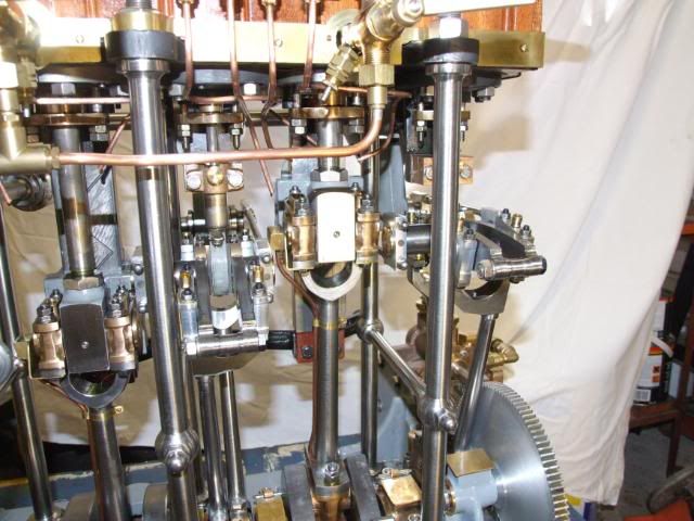
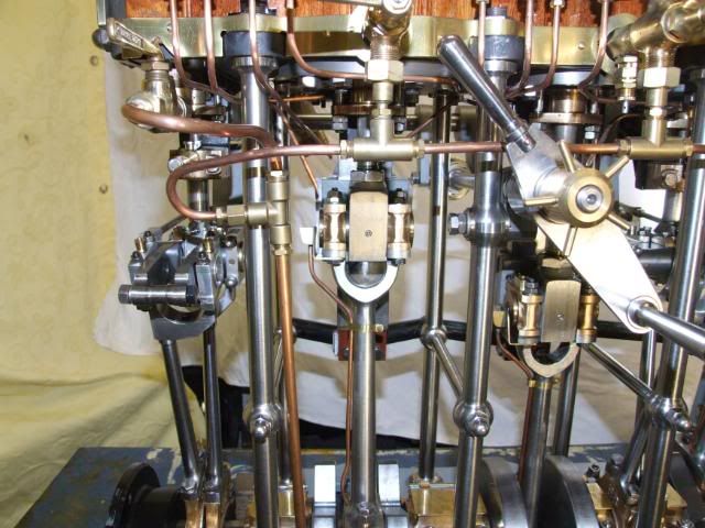
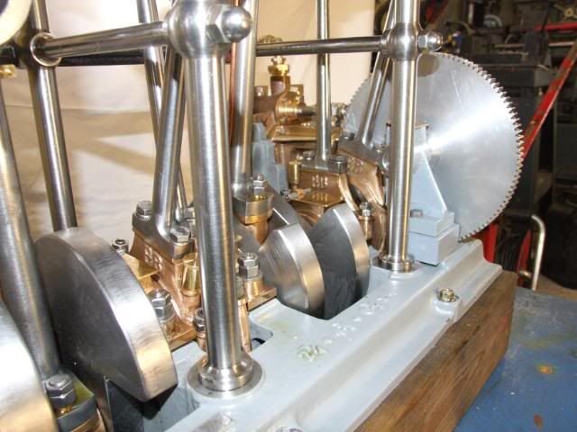
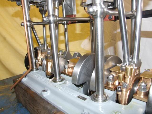
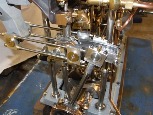
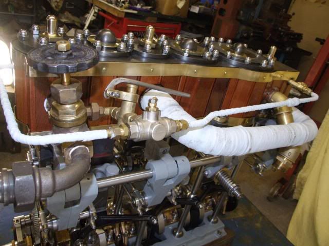
I am pleased to see that you incorporated my modification to the valve gear to move the wayshaft to port. It really makes a remarkable difference to the geometry. There is much less link jump.
It's interesting that your engine runs clockwise (from Aft) with the regulator arms close to the engine and the quadrants to starboard. Mine runs clockwise with the regulator arms away from the engine and the quadrants to port.
Any particular reason???
My engine was run on a brake on 3 occasions, the following are the results ( I wasn't able to format the table to work on the forum so you will have to juggle the figures under their correct headings):
Chest Pressures
Date RPM Boiler lbs at brake Horsepower HP IP LP Vacuum (in)
19.3.05 227 150 28 2.42 130 75 22 0
315 180 42 5.04 160 78 20 0
26.3.05 300 185 63 7.20 185 75 20 10
250 185 56 5.33 180 75 16 8
28.4.05 300 160 63 7.20 155 56 11
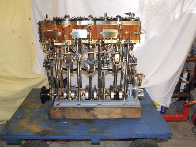
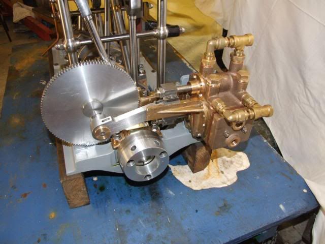
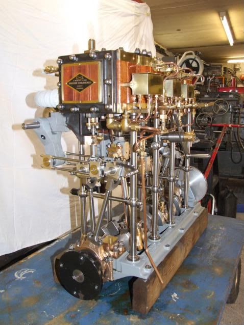
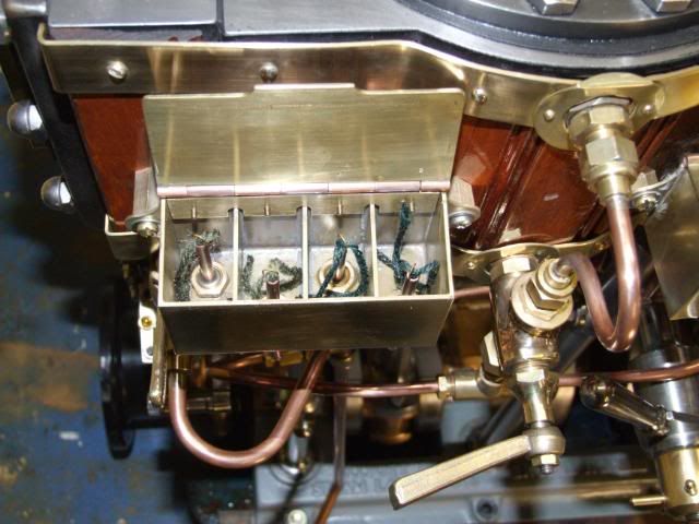
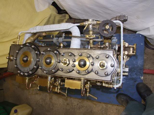
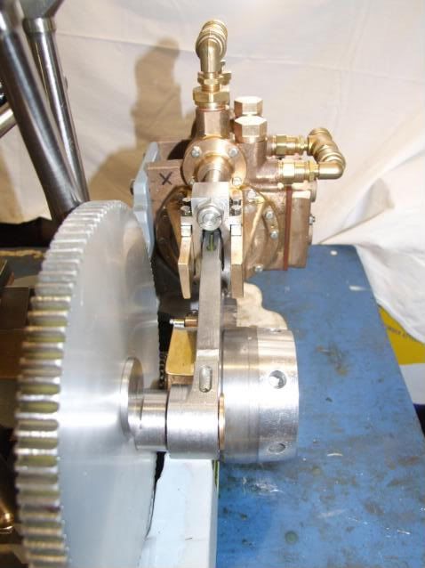
Here is a photo of the brake arrangement:
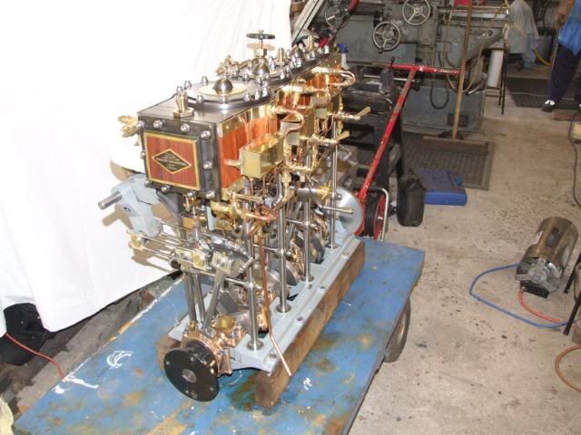
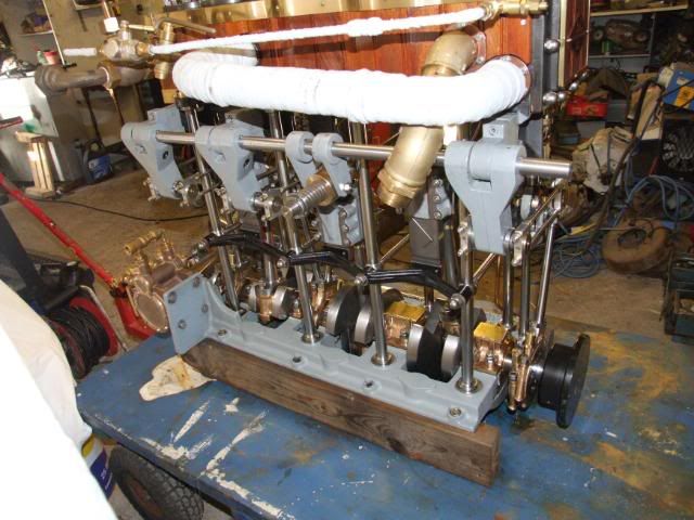
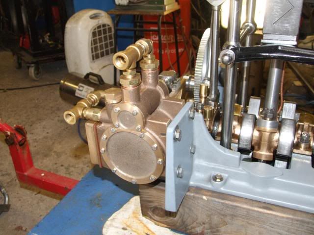
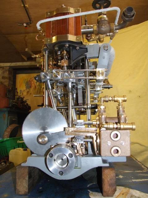
Here's one of the brake showing the inboard condenser:
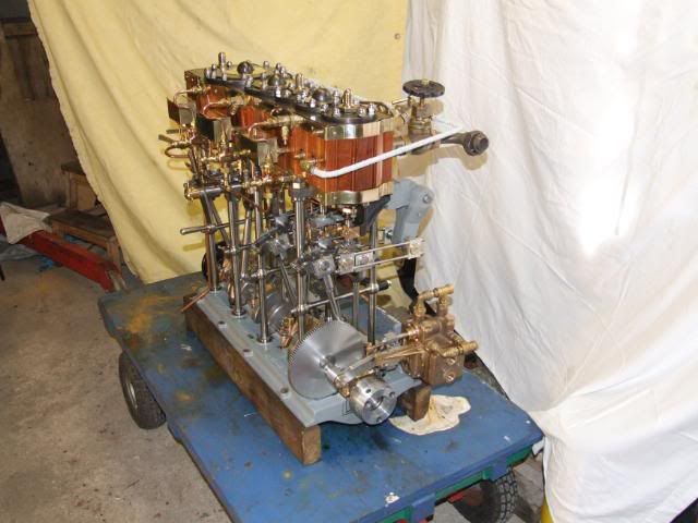
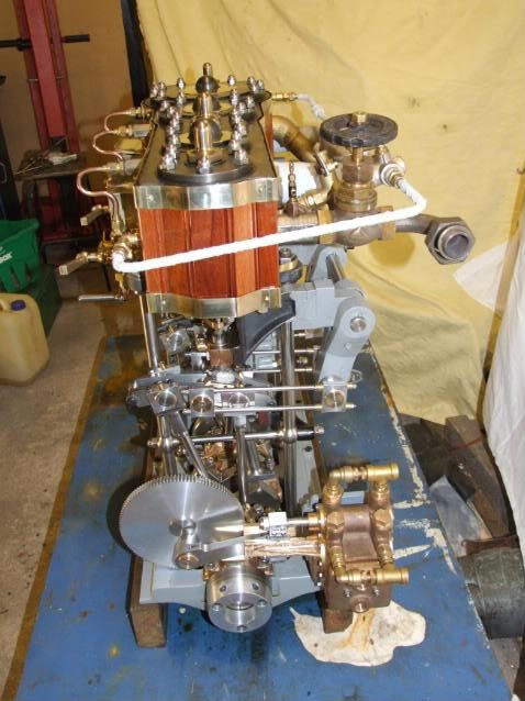
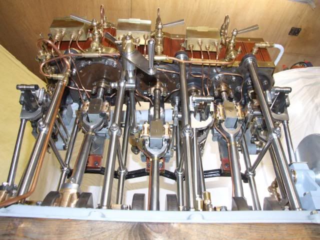
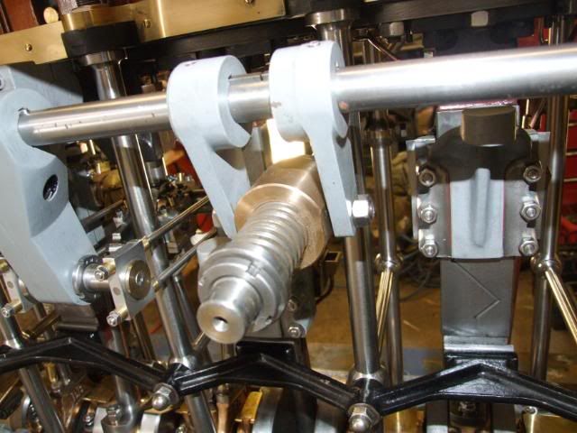
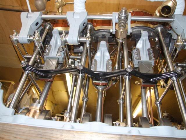
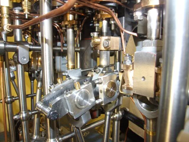
Here's another view:
On each occasion I had some difficulty balancing a big enough fire to keep the pressure up and the need for stopping and starting the engine to tend to the burning brake. I ended up with a smallish fire and extensive use of the blower to avoid the safety blowing and annoying the neighbours. I found that the pressure dropped fairly quickly when the engine was under full load. I reckon another horsepower or so was probably there if I had been able to maintain a roaring fire.
If you can decipher the table you will see that the maximum pressure on the brake was 63 lbs at a radius of 24" giving a brake horsepower of 7.2 @ 300rpm and 185psi.
My original valve calculations gave an estimated horsepower of 7.4 @300rpm so I was very pleased with the outcome on the brake. Those calculations gave an IHP of 11.4 and I used a card factor of 0.66 to estimate the BHP.
The same spreadsheet suggests that, at my maximum revolutions in the boat of 380, the engine is probably producing about 9.5 BHP
I am looking forward to more news of your progress.
Kind regards,
Peter Cowie
Sydney
SL Witch of Endor
MAGNIFICENT!
I was delighted to see the engine running on the brake and with the results you achieved under preliminary conditions.
I am pleased to see that you incorporated my modification to the valve gear to move the wayshaft to port. It really makes a remarkable difference to the geometry. There is much less link jump.
It's interesting that your engine runs clockwise (from Aft) with the regulator arms close to the engine and the quadrants to starboard. Mine runs clockwise with the regulator arms away from the engine and the quadrants to port.
Any particular reason???
My engine was run on a brake on 3 occasions, the following are the results ( I wasn't able to format the table to work on the forum so you will have to juggle the figures under their correct headings):
Chest Pressures
Date RPM Boiler lbs at brake Horsepower HP IP LP Vacuum (in)
19.3.05 227 150 28 2.42 130 75 22 0
315 180 42 5.04 160 78 20 0
26.3.05 300 185 63 7.20 185 75 20 10
250 185 56 5.33 180 75 16 8
28.4.05 300 160 63 7.20 155 56 11
Here is a photo of the brake arrangement:
- Steaming 26.04.05 Prony Brake small.jpg (147.98 KiB) Viewed 19772 times
- Brake Setup1.jpg (131.89 KiB) Viewed 19772 times
- PICT0005asmall.jpg (142.75 KiB) Viewed 19772 times
If you can decipher the table you will see that the maximum pressure on the brake was 63 lbs at a radius of 24" giving a brake horsepower of 7.2 @ 300rpm and 185psi.
My original valve calculations gave an estimated horsepower of 7.4 @300rpm so I was very pleased with the outcome on the brake. Those calculations gave an IHP of 11.4 and I used a card factor of 0.66 to estimate the BHP.
The same spreadsheet suggests that, at my maximum revolutions in the boat of 380, the engine is probably producing about 9.5 BHP
I am looking forward to more news of your progress.
Kind regards,
Peter Cowie
Sydney
SL Witch of Endor