The casting date goes to the future every month because I have to many parallel fun projects
I first will have a look how it comes out of the sand. If it is OK, I will pour some more of it - but no fixed scedule jet...
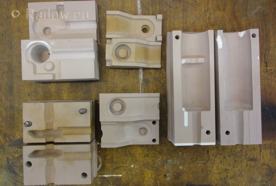
The core box making is still in progress. Unfortunately, the used CNC milling machine has a spindle error in the X-axis. So it generates "arbitrary" marks in the material. I have to rework this.
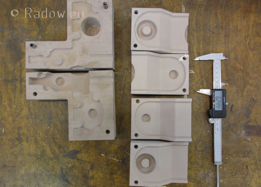
Full set of HP-cores are ready machined
LP-piston valve top and LP cannels
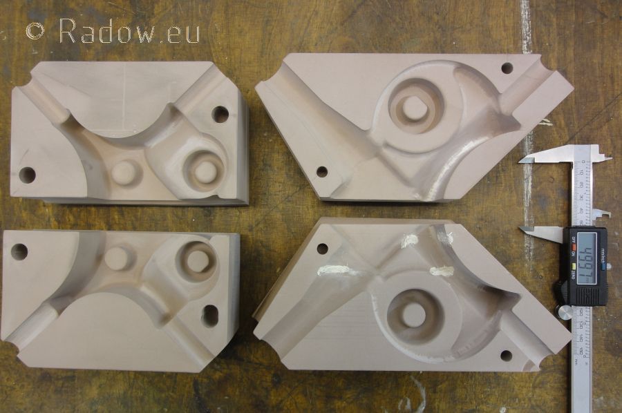
Parts of the receiver (left) and LP exhaust (right)
Cylinder pattern
Posted: Wed Sep 05, 2012 1:46 pm
by Rainer
Hello Steamboaters out there.
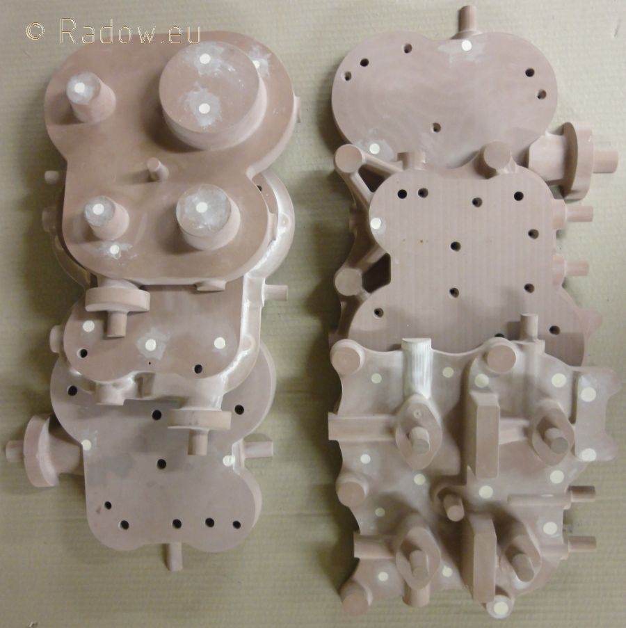
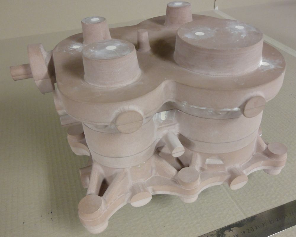
Today I can show you the cylinder pattern for my 1:2 modell of the "Steam Pinnace Engine of the German Imperial Navy" from around 1910.
To mount all steam canal cores at the right position it is necessary to slice the cylinder pattern and the mold build by it. This 6 plates will form the outer shape of the cylinder block. They are in the size of about 270 x 270 mm each (10 7/12 x 10 7/12 inch).
Front view
The five round drums at the top are the core marks for the two pistons, the two piston valves and the receiver cores.
HP at the left, LP at the right. Live steam inlett at the rear left.
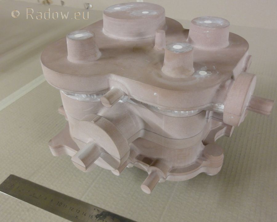
Back side view
Live steam inlett at the right. Exhaust in the middle. So all steam connections will be build by the cores inside of the cylinder block!
Video of making the Cylinder Block Parts
Posted: Wed Sep 05, 2012 2:08 pm
by Rainer
This Video was made during machinig the cylinder block parts. I had to use the 5-Axes HERMLE mill at work because of the size of this parts.
We had some trouble to teach the CAM program - which generats the mill movement code from the 3D modell - how to do the job most efficiently because of the complex cylinder conture - or because of the stupid program/user? ...
From some of the fast moves you could estimate how fast this mill could work if fed with a good program...
We let in run during night so we did not care about machining time.
Re: First core bockes
Posted: Wed Sep 05, 2012 5:13 pm
by DetroiTug
Rainer,
Nice work as always. Looks as though the code was produced with a G61 "Exact stop" mode. Where the machine stops after every command. Try replacing it with a G64 "Constant velocity" mode. It will shorten the machining time. Where the interpreter will blend the moves one to the next, and even look ahead multiple lines to plan the trajectory.
A very powerful and inexpensive program to produce G-codes from 3D models is Vectric Cut3D. An inexpensive and easy to use modeler with STL export is Moi3D.
What is the material being machined?
-Ron
Re: First core bockes
Posted: Wed Sep 05, 2012 5:46 pm
by Rainer
DetroiTug wrote:Looks as though the code was produced with a G61 "Exact stop" mode. Where the machine stops after every command. Try replacing it with a G64 "Constant velocity" mode.
You got it! We found out this later. Because I don't operate this machine and the operator never programmed such 3D shapes before we missed to remove the G61.
With the G64 we got faster moves but the strategie to remove the material is still lousy for a 20 K$ 5-axis program ;-(
DetroiTug wrote:A very powerful and inexpensive program to produce G-codes from 3D models is Vectric Cut3D.
I used Cut3D with a smal "hobby mill" in a friends shop - in the moment I have lent a mill from an other friend including the computer with MeshCam. A little long winded to get the complete worpiece done - especialy with steep and deep/high walls - but after a while I got good results with it.
DetroiTug wrote:What is the material being machined?
It's "SikaBlock® M650" - (see post from 02 Feb 2012, 20:18 above)
Happy end with new mill
Posted: Thu Sep 06, 2012 2:43 pm
by Rainer
This is the full story of machining the core boxes with happy end. I first had truble with the available hobby CNC mill I could use becaus it has a defect in the x-Axis. This ruined some parts or produced a lot of rework with putty and sandpaper.
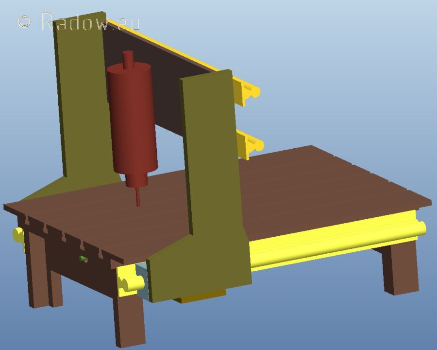
So I decided to build my own CNC-mill. I could enthuse my friend Dieter that he also would need such a machine. After my first rough design at the 12th of February 2012 we have made the agreement that he has to build the wooden pattern and I would have to take care of the casting and the machining of the table.
Dieter had finished his job 5 days later.
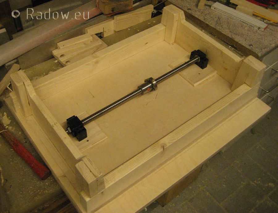
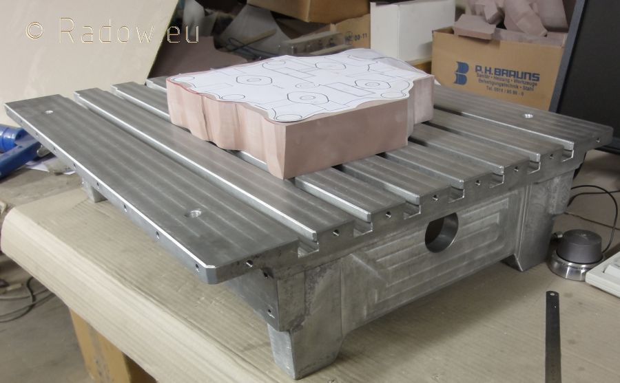
About 4 weeks later we could put his and mine 35 kg cast aluminum bases on the "big mill". My colleague Thomas (bottom left) did the machining according to my design.
Here you can get an imagination of the possible workpiece size while placing my cylinder modell with it's raw material on the table. The table size is 600 x 500 mm (24" x 20") with a spindle travel of 400 x 400 x 130 mm (16" x 16" x 5").
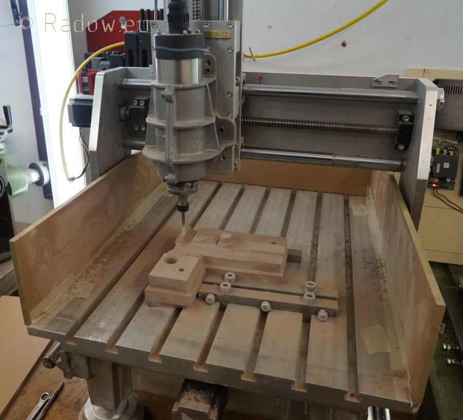
My mill table is still sitting naked under the work bench as shown above - waiting for building capacity of mine. But my friend Dieter found some time to design and build the rest of his mill while I bought the stepper driver to combine it to a CNC mill.
This are videos from the first test runs in April 2012.
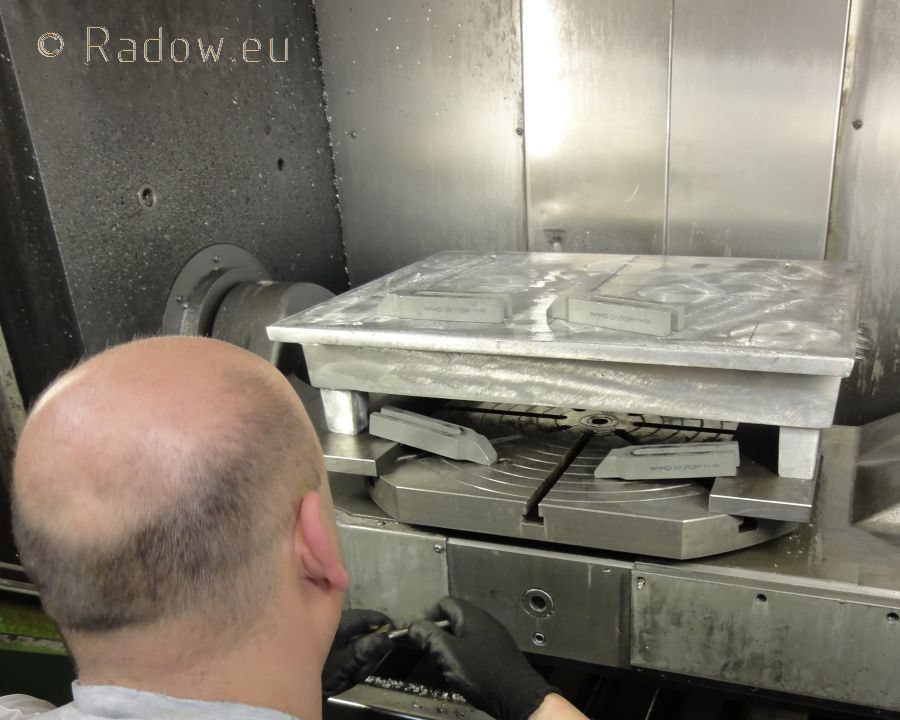
Last week Dieter delivered his mill into my shop. With it I could finish the cylinder core box making in a flash. I am operating it with a 5 mm ball nose mill at 17,000 rpm and a 1.1 kw 3 phase spindle. I limited the max travel to 3000 mm/min (120 inch/min).
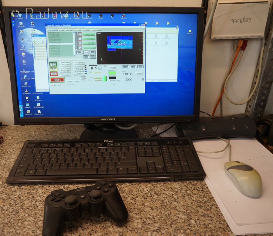
I am running the CNC-Mill with the common Mach3 software. To maneuver the mill by hand I coupled it with an ordinary 25$ wireless kids game controller.
At least here you can see all ready machined cylinder core boxes
Re: First core bockes
Posted: Thu Sep 06, 2012 2:53 pm
by fredrosse
Really wonderful to see this work being done here. I am an old "hand turned dials" machinist, and can clearly see that those methods are very far obsolete in todays world. Thanks for showing your excellent progress, it is all first class.
LP - cores
Posted: Fri Sep 07, 2012 11:34 pm
by Rainer
Hello Fred
- because of my limited English I don't know the usual polite phrases to answer you in the right way
I just say THANK YOU
This weekend I plan to build all cores to test if everything fits together.
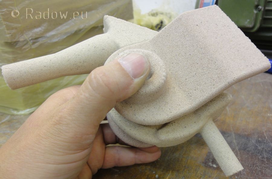
This are the LP ports and exhaust pipe cores. This is just how they came out of the core boxes - no rework necessary!
Here you can see how it goes together. Later the cores will be glued together.
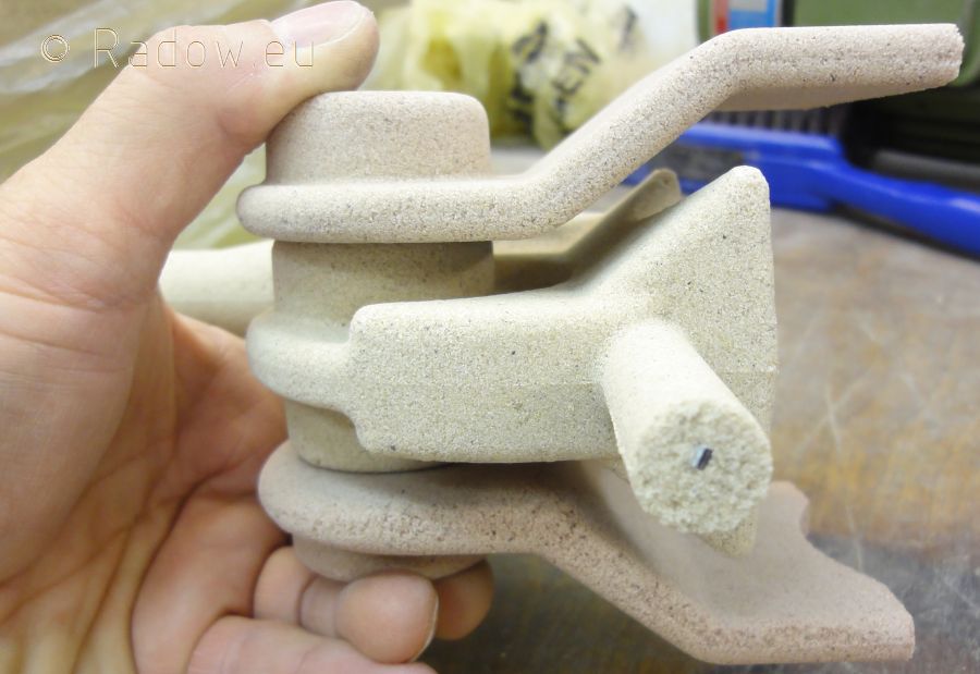
An other perspective. The metall piece inside of the core mark is a reinforcement bar. The overall minimal design wall thickness is 9 mm. So even if the cores don't sit at the right position there will be left enough material.
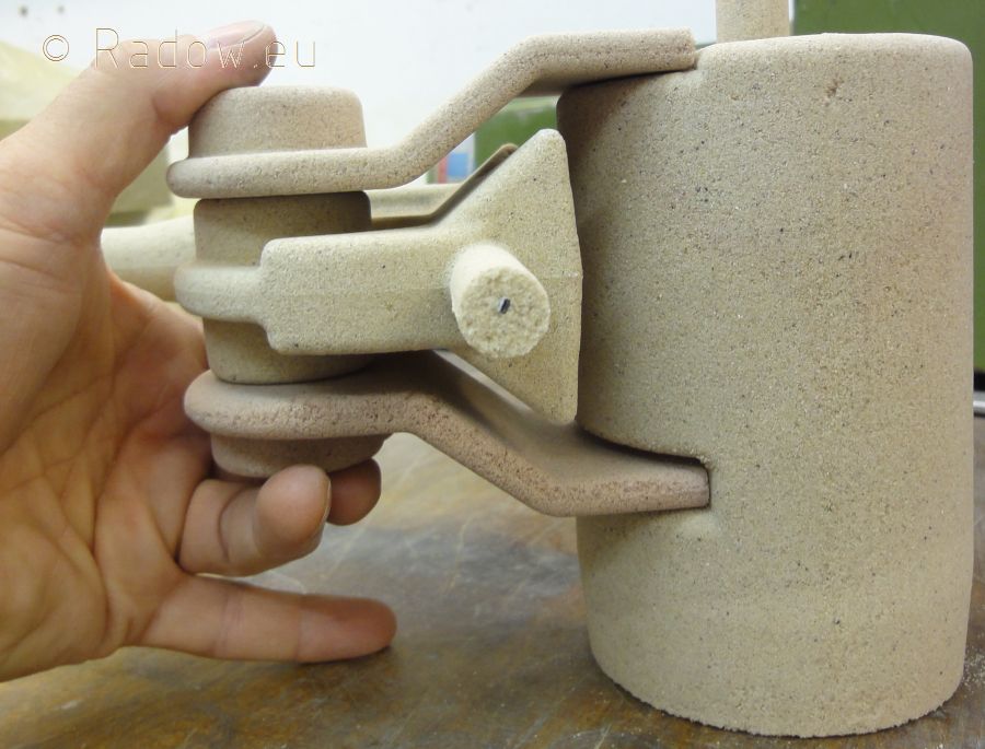
All together incluing the LP cylinder core.
Re: First core bockes
Posted: Mon Sep 10, 2012 2:11 pm
by S. Weaver
Rainer:
Nice!
Re: First core bockes
Posted: Mon Sep 10, 2012 5:42 pm
by gondolier88
Hi Rainer,
Your work is inspiring to say the least. I'm really enjoying seeing your progress, which is very quick as well.
One question- your last picture shows the ports going into the cylinder- yet the bottom port is well above (50mm?) what would appear to be the bottom of the cylinder- why is this?