Hi Mike
The poppet is drilled progressively and has a 129mm2 open area at full throttle and is yet to be tig welded to the valve stem, it assembles from the poppet end and I am using 2, 5/16-1/16 viton Orings for the gland seal, I saw the design in a steam boat manual and used the idea. I am wondering if it would be better if instead of drilling holes in the poppet three v shaped slots around it's circumference would be better, anybody have any thoughts on this?
Noel
Three Drum Boilers
-
Lopez Mike

- Full Steam Ahead

- Posts: 1903
- Joined: Wed Dec 07, 2011 6:41 am
- Boat Name: S.L. Spiffy
- Location: Lopez Island, Washington State, USA
Re: Three Drum Boilers
Cool. About how much travel is there from closed to full open. Not in turns but in linear motion. I'm fond of lever controls and might see if I could make it work that way.
Mike
Mike
If you think you are too small to make a difference, try sleeping with a mosquito.
Dalai Lama
Dalai Lama
-
Kiwi Noel
- Lighting the Boiler

- Posts: 27
- Joined: Sun Jan 15, 2012 10:03 pm
- Location: Timaru, New Zealand
Re: Three Drum Boilers
Travel from from closed to fully open is 14mm or 9/16" which ever you prefer, I won't be using this as a shut off, the main valve will be on the
steam line to the engine at the boiler manifold. I like your idea of it being linear operated something I never thought of doing I will put my thinking cap on.
Noel
steam line to the engine at the boiler manifold. I like your idea of it being linear operated something I never thought of doing I will put my thinking cap on.
Noel
-
Lopez Mike
- Full Steam Ahead
- Posts: 1903
- Joined: Wed Dec 07, 2011 6:41 am
- Boat Name: S.L. Spiffy
- Location: Lopez Island, Washington State, USA
Re: Three Drum Boilers
I'm used to North American locomotive practice where the throttle lever operates on a quadrant as does the reverse gear. The engineers do a fair amount of adjusting the valve gear and throttle settings as the loads and the throttle openings often vary independently of each other. We boaters spend as little time as possible either climbing or descending serious grades!
I believe European (at least British) rail practice is to use rotary motion for the throttle. Someone more knowledgeable should chime in here.
U.S. (as well as Russian and Chinese) practice is to have a push/pull rod to the throttle connected to a point near the pivot of a throttle lever which slides along a quadrant made of a fairly fine rack. There is a lever on the end of the throttle that disengages a blade or a short segment of rack that matches the quadrant rack so that you can move the throttle and then lock it.
This one has an ingenuous arrangement to get a finer adjustment. In this case, the throttle rod disappears through a packing gland as the throttle is in the steam space of the boiler, a practice that was common until the 1920's or so. Why the picture is rotated so that the rear of the boiler is up I have no idea. With Google, you take what you can get.
http://i980.photobucket.com/albums/ae28 ... _0034a.jpg
Most American locomotives use a poppet valve but by the middle of the nineteenth century had gone to a balanced poppet valve with one diameter slightly smaller than the other as the pressure loads has risen so high that the engineer had difficulty opening the throttle.
The throttle was in the steam dome until perhaps the 1920's. Then it was moved to the smoke box at the front for ease of servicing. As you may know, with locomotives the boiler is a major structural member. When the boiler grew in length with heat, the internal throttle rod grew too. But with a front end throttle, the rod ran down the outside of the boiler and there was a serious problem with differential changes between the boiler length and the rod length. Throttles that were closed at rest sometimes didn't stay so! The solution was to interrupt the rod half way along its length with a pivoting lever. This reversed the direction of motion as a side effect of eliminating the differential length changes. The lever is visible on many portraits.
Maybe we should get back to three drum boilers. My apologies.
Mike
If you think you are too small to make a difference, try sleeping with a mosquito.
Dalai Lama
Dalai Lama
-
artemis

- Full Steam Ahead
- Posts: 465
- Joined: Wed Nov 18, 2009 4:13 am
- Boat Name: Pond Skimmer
- Location: Portland, Oregon, USA
- Contact:
Re: Three Drum Boilers
Would love to have such an article. Drop me a PM, please.PeteThePen1 wrote:Hi Noel
As a pusher of paper rather than a machinst I am totally in awe of the work you have done on the boiler and especially the Reflex gauge glass. I have copied all the pictures of how you made it, though I doubt if I could ever copy it. Have you thought of doing an article for Ron Fossum's Steamboating Magazine - "How to make a Reflex Gauge"?
Regards
Pete
-
Kiwi Noel
- Lighting the Boiler
- Posts: 27
- Joined: Sun Jan 15, 2012 10:03 pm
- Location: Timaru, New Zealand
Re: Three Drum Boilers
I have been lent a wire bound photo copied Steamboating mag issue number 56 winter 1994 and in it is an article by Wally Mounster describing the throttle valve that I have just made, it is good to know who designed it.
Noel
Noel
-
Kiwi Noel
- Lighting the Boiler
- Posts: 27
- Joined: Sun Jan 15, 2012 10:03 pm
- Location: Timaru, New Zealand
Re: Three Drum Boilers
Health problems finally behind me so back to finishing the boiler fire bricks and insulation fitted, casing painted and assembled. This is the part when there is a great out flow or money especially 300 PSI steam rated valves I still have to get a safety valve and sort out the piping from steam drum to the super heater the designer suggests I use a Bailey Birkett 707 safety valve because of the temperature and 15 mm Yorkshire GHD bronze fittings and Cupronickel pipe because they make any maintenance easy, more items to import thank goodness for the internet and Papal.I have uploaded the latest photos on to photobucket, the link http://s1150.photobucket.com/albums/o618/KiwiNoel/
Noel
I like this quote by Charles Spurgeon
Wisdom is the right use of knowledge.To know is not to be wise ...But to know how to use the knowledge is to have wisdom.
Noel
I like this quote by Charles Spurgeon
Wisdom is the right use of knowledge.To know is not to be wise ...But to know how to use the knowledge is to have wisdom.
-
TahoeSteam

- Full Steam Ahead
- Posts: 814
- Joined: Fri Mar 07, 2014 5:38 am
- Boat Name: Wayward Belle
- Location: South Lake Tahoe, CA, USA
- Contact:
Re: Three Drum Boilers
What a beautiful project! I'm glad you were able to get beyond your health issues.
~Wesley Harcourt~
https://www.youtube.com/c/wesleyharcourtsteamandmore
https://www.youtube.com/c/wesleyharcourtsteamandmore
-
Mike Rometer
- Full Steam Ahead
- Posts: 936
- Joined: Sat Aug 13, 2011 6:41 pm
- Boat Name: B.N.Y.S.
- Location: Middle Earth
Re: Three Drum Boilers
In the local vernacular, "Crackin' job inerit?" 
Retirement is about doing what floats your boat!
A BODGE : - A Bit Of Damn Good Engineering.
A BODGE : - A Bit Of Damn Good Engineering.

Re: Three Drum Boilers
Just browsing around, and I should thank Kiwi Noel who's pictures provided the confidence we needed to set to on a set of three of these. ...and yes drilling the 1400-odd 12.1mm holes did take a while 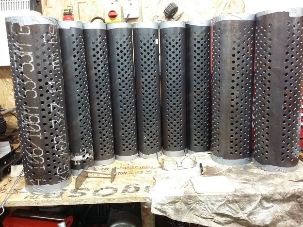
We also made a chain-driven contraption, but managed to remachine the square on the expander so that we could get the whole thing into the mud drums. And also used this to drive a countersink to de-burr the holes.
Just finishing the ends for the drums. Next I need to borrow a more modern lathe to screwcut the M16 and M20 threads on the stays. Pressure tested the superheaters and economisers and these are good and tight at 500psi, and will hold most of that pressure overnight (pipe-work weaping steals a few PSI).
Next task is to make the reflex gauges (castings ordered) and fit all the ceramic fibre-board insulation.. As always pics and word on the blog (including video of expanding contraption and hydraulic testing)....
https://sy-befur.co.uk/2017/04/03/tube- ... r-headers/
...and then we need to design an installation plan (lots of fittings and plumbing in the next few months)